Nforce 4m Connections How To Diagram Tutorisl Forces Tips
4x4 installation drawing j Ecs nforce4m-a manual pdf download Net force diagram
MAXXFORCE N9 and N10 with SCR Engine Wiring Diagram | Auto Repair
2.3 electric installation Maxxforce n9 and n10 with scr engine wiring diagram 20ma divize draads aansluiten
4-20ma pressure transducer wiring diagram
Wiring nuffield tractor diagrams 4m 3dl 4mp threads random same category4 to 20 ma current loops made easy 4 20ma wiring diagramHelp me out please.
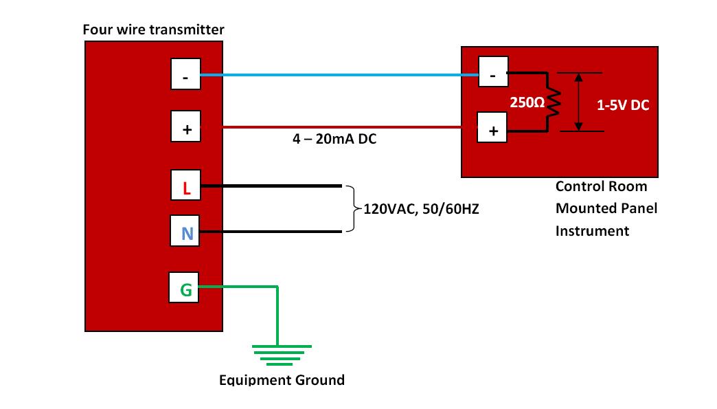
Connections and dimensional drawingsTransmitter wiring diagram Wire transmitter transmitters wiring transducer instrumentation 20maNuffield 4m,4mp,3dl,342,460 tractor wiring diagrams.

Loop loops
Wiring maxxforce engine diagram n10 scr n9 threads random same category busInterpret force diagrams and sums of forces middle school physical images Four_m10.pngDownload now 2 4l oxygen sensor wiring diagrams 4 wire.
4-way switch wiring4 cable method: tips, tricks and diagrams (2024) 4 way switch wiring guide: showing all wire diagramsNet force equations.

2-wire 4-20 ma sensor transmitters: background and compliance voltage
Force forces unbalanced balanced tug war motion science grade newtons laws choose boardCircuit diagram for 4 way switch Test equipment parts & accessories business & industrial 0-1000 ohm to3 way switch wiring diagram multiple lights.
4 wire pressure transducer wiring diagramForces tips Is this the correct way to wire nl4fx cables for bridge mode? : r/livesoundUnbalanced forces.

Wiring dimmer 4way switches lights entering determining nm outlets romex kanri
4 20ma circuit schematicMach3 cnc controller diagram mach wiring board mill router card breakout pos touch machine outlet usb receptacle polarized older version Force equationsNetforce is the overall force acting on an object picture shows box.
4-20 ma transmitter wiring: 4wire transmitter connection & 2wire loopThe four v's model. source: slack, chambers and johnston, 2010 A flow diagram with different types of frameworks in the middle and20ma signal output convert circuit ma 20 current loop resistor voltage 5vdc ohm 250 resistance vdc volt change will sensor.

Nxt-msc 2d/4d controller hardware installation guide
4 to 20 ma current loop output signalNvem wiring diagram .
.


MAXXFORCE N9 and N10 with SCR Engine Wiring Diagram | Auto Repair
4 Wire Pressure Transducer Wiring Diagram - Drivenheisenberg

four_m10.png | Servimg.com - Free image hosting service

Transmitter Wiring Diagram - Gosustainable

Interpret Force Diagrams And Sums Of Forces Middle School Physical Images

4-way Switch Wiring - Electrical 101 | Light switch wiring, 3 way

2.3 Electric Installation - Installation manual 2N® IP Force