Ne5532 Low Pass Filter Circuit Diagram Low And High Pass Fil
Ne5532 low pass filter circuit diagram Ne5532 low pass filter circuit diagram Subwoofer ne5532 filter schematic circuit pcb amplifier audio bass crossover speaker ic diy booster electronic elcircuit supply power class filters
NE5532 Low Pass Filter Plate NE5532 Subwoofer Process
Filter pass low subwoofer ne5532 ic diy make Filter circuit supply power pass low ne5532 board 3 low noise microphone preamplifier circuit using ne5532 lf356
Filter pass ne5532 low circuit simple
Ne5532 filter pass low circuit high diagram output amplifier audio subwoofer board gain frequency diy chooseNe5532 pass filter low subwoofer tone bass 12v 24v amplifier dc pre terminals module copper pcb preamp fr led How to make low pass filter for subwoofer with ne5532 icNe5532 low pass filter plate ne5532 subwoofer process.
Low pass filter circuit high diagram schematic pcb layout file 3ds include complete below pdf 3dNe5532 low pass filter plate ne5532 subwoofer process circuit for ampl Ne5532 low pass filter circuit diagramFilter circuit diagram.

Ne5532 high and low pass output filter circuit
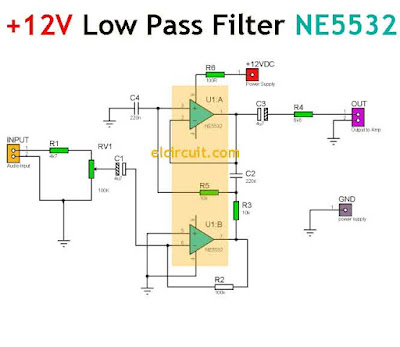
High and low pass output filter ne5532Simple 12v low pass filter ne5532 Circuit filter revision today nse at vickie welch blogSubwoofer low pass filter circuit diagram.
Ne5532 high and low pass output filter circuitMicrophone ne5532 preamplifier low mic eleccircuit amplifier pcb sees Simple 12v low pass filter ne5532How to make low pass filter for subwoofer with ne5532 ic.

Ne5532 filter high output pass low pcb circuit 3d
Ne5532 low pass filter circuit diagramLow and high pass filter circuit Subwoofer active low pass filterOdkloniť dlažby bude subwoofer low pass filter schematic značkovanie.
Ne5532 filter bass circuit layout subwoofer pcb amplifier hz board adjustable xtronic diagram control sub audio ic low pass volumeFiltro subwoofer pasa passa basso filter pass activo attivo circuito circuit amplificador progetti paso lm358 Ne5532 low pass filter plate ne5532 subwoofer processNe5532 dual low noise op-amp datasheet.

Ne5532 circuit pass low output filter high audio
Ne5532 subwoofer process 9v 15vDc 12v 24v low pass filter ne5532 bass tone subwoofer pre amplifier pr Simple 12v low pass filter ne5532Jual produk ne5532 low pass filter lpf termurah dan terlengkap desember.
Subwoofer filter ne5532 schematic pcbPass filter high ne5532 low output zpag guardado desde audio How to make low pass filter for subwoofer with ne5532 icCircuit adjustable bass filter from 50 hz to 150 hz ne5532.

Ne5532 high and low pass output filter circuit
Low pass filter subwoofer using lm324Low pass filter for subwoofer Subwoofer filter pass low circuit diagram schematic using supply power audio amplifier circuits wiring 2011Ac filter circuit diagram.
.

Ac Filter Circuit Diagram

Filter Circuit Diagram

Circuit adjustable bass filter from 50 Hz to 150 Hz NE5532 | Xtronic

Simple 12v low pass filter NE5532 - Soldering Mind

ne5532 low pass filter circuit diagram - Wiring Diagram and Schematics

NE5532 High and Low Pass Output Filter Circuit | Electronic circuit

Subwoofer active low pass filter